
HOW TO FIT A ROLLER GARAGE DOOR
- Step 1 – Pre-Installation Checks & Components
- Step 2 – Guide Channel Preparation & Fixing
- Step 3 – Box & Barrel Assembly
- Step 4 – Fixing of Frame
- Step 5 – Installation of Curtain
- Step 6 – Setting the Limits / Fitting Control Unit
- Step 7 – Installation of Lid & Overrides
- Step 8 – Final Checks / Commissioning
Want to fit it yourself?
Download our Self Survey Form.
Step 1 – Pre-installation Checks & Components
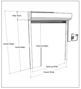
Widths
Overall Width = Opening Width + Guides
Guide widths vary dependent on specification.
Heights
Overall Height = Guide Height + Box Height
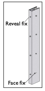
On face fix installations, please make an allowance for the bottom rail projection within the guide channels and a bottom “guide” channel as necessary.
N.B. For reveal fix installations the box and guide channel sizes would be included and the opening /overall size is the same.We recommend the surveyor deducts 5mm for tolerance when reveal fixing
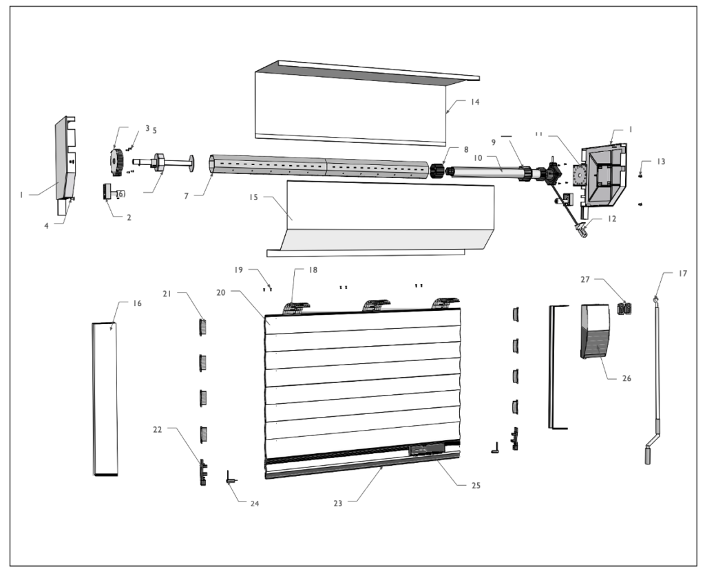
- End plate
- Roller wheel
- Safety brake / captive bearing
- Screw for roller wheel
- Screw for safety brake
- Floating shaft end
- Steel tube
- Motor drive end
- Motor collar
- Tubular motor
- Motor fixing plate
- Override eyelet
- Screw for motor head
- Enclosure (back box)
- Enclosure (lid)
- Guide channel
- Override handle
- Selve locking strap
- Selve locking strap screw
- Curtain slat
- Curtain slat end lock
- Bottom bar end lock
- Rubber weather seal
- Optical safety edge sender / receiver
- Optical safety edge transmitter
- Control panel
- Radio remote control handset
Once you are sure that all components are present, correct and damage-free, you can continue with installation.
Step 2 – Guide Channel Preparation & Fixing
Guide Channel Preparation
If the guides need cutting down refer to Section 1: Pre-Installation Checks and Components. If face fixing the guide height should be at least 50mm above the structural opening to maximise drive through height.
- Position guides
- Drill a minimum of 4 fixing holes (7mm pilot hole 10mm outer hole), avoiding mortar joints and other
N.B. Guides are handed. If cutting guides cut excess length from bottom of the guide. Incorrect handing will result in the back of the guide not lining up with the back of the box.

Guide Channel Fixing
When fixing it is essential that guide channels are perpendicular to each other. Packers may be required for masonry which does not offer a flush surface. Fixings will be specified during the survey stage.
Guides must always be level and fixed firmly. Fix guides with the appropriate screws and apply the covering buttons. Ensure that the fixings used are suitable for the wall structure.

Step 3 – Box & Barrel Assembly

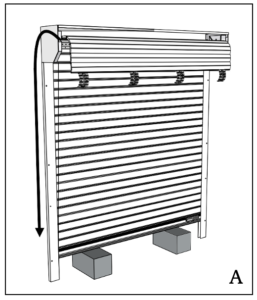
The motor barrel is held in place by a captive bearing (Compact) or safety brake (Classic) on the non-drive end, and a mounting plate on the drive end.The non-drive end of the barrel has an adjustable shaft held in place by a fixing bolt. Loosen the fixing bolt allowing the shaft to slide in and out of the motor barrel (see Drawing A).
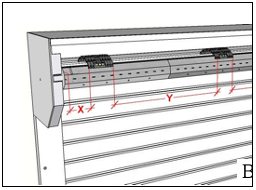
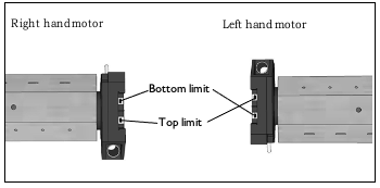
Using the two counter-sunk bolts and nuts supplied, fit the barrel into position, making sure that the manual override position on the motor is at the required point, limit switches are visible and that the motor is fitted to the correct side of the enclosure (see Drawing B).
Once the motor barrel is installed, tighten the motor plate and fully extend the sliding shaft into the free bearing or safety brake at the non-drive end. Lock the shaft with a fixing bolt.
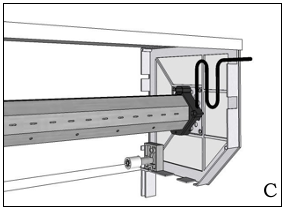
Drip Loop
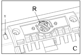
The motor power lead should be positioned tightly against the end plate. Create a drip loop in the cable to prevent water from running down the cable and into the motor (see Drawing C).This can be fixed in place using cable ties.
Step 4 – Fixing Of Frame
Ensure the pillars, lintel and header are free from sharp objects or bumps before positioning the frame. Obstacles such as these may twist the guides or distort the fascia..
- Slot end plate pegs into guides (see Drawing A), remembering the guides are handed. Check guide terminals are in place if appropriate (see Drawing C).
- Position guides and fascia against
- Fix guides/end plates with minimum 2 1/2” x 10 screws (and plugs to masonry / timber or 1” x 10 self tapping screws to steel. Fix fascia every metre with minimum 1” x 10 screws. Fixings should be spaced uniformly to assist with load
N.B.The end plate pegs are not designed to carry the weight of the door. It is important to fix the end plates into the wall and to take care when manoeuvring the door to avoid snapping them.

When the frame is fully secured to the structure you are ready to begin curtain installation.
Step 5 – Installation Of Curtain
- Unwrap the curtain from its packaging and lay the roll on a clean and level
- Wrap the barrel in the packaging to prevent damage to the
- Lift the curtain - begin to unravel the curtain, bottom rubber and rail over the barrel and into the guides (see Drawing A).
- Locking straps must be fitted before the curtain is fully unravelled. Position blocks between the frame for curtain to rest on while securing locking
- Secure Selve locking straps
The Selve locking system must be fixed to the shaft as follows:
Slide the locking straps onto the last slat of the curtain while the last slat hands over the shaft.
The Selve fixation should have a distance X of between 30mm and 80mm (see Drawing B).
We recommend a minimum of one fixation per 600mm length (Y) of octagonal shaft.
Line the clamps of the Selve lock with cutting hole Y (see Drawing C). Turn slot X by using a coin in direction of arrow as far as it will go. Attention - when turning the slot X the clip snaps into place.
In addition, please ensure that you use two 4.2mm x 9.5mm Pozi Pan Head Screws (as supplied) to securely fix each Selve fixation.
N.B. Providing you use the correct fixings, they will not come into contact with the concealed tubular motor. The motor can be damaged if other screws are used.
The last slat of the roller shutter must not protrude from the guide rail by more than half of the profile height.
The “anti-lift effect” only works if the individual parts support one another and the upper roller shutter profile is pressed downwards.
Step 6 – Setting The Limits / Fitting Control Unit
Once the Selve locking straps are attached, use manual override loosely to take the shutter half way up. Remove manual override ready for fitting in later stages. Remove blocks ready to fit panel.
Setting up the control panel
When connecting to an electricity source, the limitations of the Low Voltage Directive should be observed. Connections to the 230V mains supply must be made by a competent person.The arrangement and positioning of the electrical control panel should be such that the operator can see the door, and should be on the motor side.
Use of the control panel instructions
Please refer to the individual control panel instructions for mounting and commissioning.The instructions include important safety information and should be left with the end user.
Individual panel models dictate the relationship of fixings to each other.

NRG Motor
It is recommended to attach the motor to a test lead. Please refer to separate limit setting instructions attached to the barrel.
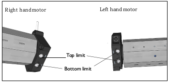
Somfy Motor
Fully press in limit switch to activate. Press and release the switch when door has been set to stop in correct position.
Replace the yellow limit switch cover cap once limits are set.
Step 7 – Installation Of Lid And Overrides
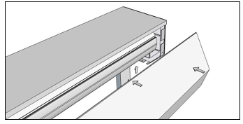
Put the front lid inside the horizontal channel of the back box. Manoeuvre the lid into the whole channel across the length, and allow the lid to lie flat vertically down.
Use screws or rivets (supplied) to fix the front lid in place.
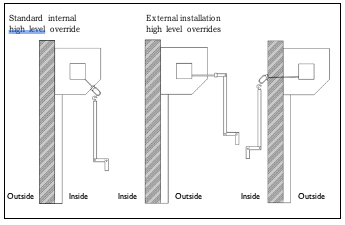
Standard Manual Override
- Drill hole for override eye through end plate flange.
- Insert override eye in hole in motor adjacent to limit
- Insert and tighten the holding screw and washer from
- Hook crank handle in
- Secure clear of shutter with crank handle
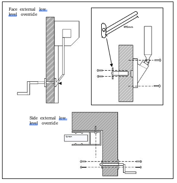
Optional Low Level External Override
Please note more detailed installation instructions are supplied in the override kit.
- Drill hole for override eye through end plate flange.
- Insert hexagonal bar through hole in motor adjacent to limit adjusters.
- Mark position for hole through wall adjacent to guide rail at bottom end of crank. Crank can exit at 90o if door tight to return Length of shaft can be shortened to adjust operating height.
- Drill 22mm hole through the
- Secure universal joint bracket to
- Insert tube (cut to length) and fix plate to
N.B. Fixings not supplied.
Step 8 – Final Checks And Commissioning
- Remove any protective plastic coverings from guides, slats and enclosure
- Wipe curtain with a damp
- Check that all electrical and operating equipment is installed correctly and
- Apply the manual override direction as appropriate, depending on whether the handle should be turned one way or the other to raise or lower the door
- If the door is fitted externally, apply a bead of silicone around the box edge to prevent water
- Complete paperwork within the Operation & Maintenance Manual. The installer should retain one copy of the Declaration of Conformity as a record and leave the other with the door.
- Instruct the customer / end user in the use of the door and manual